


ML-CPK-R Series

•Easy operation with touch pad
•Histogram display, Panel size: 93×93mm
ML-CPK-R Series
The precise indicator:
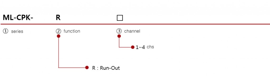
The calibration for miniature 1~4chs / Run-out, Roundness, Concentricity
The slim and light-panel type, 1~4 chs
3.5 TFT COLOR LCD TOUCH
Peak-Peak
Frequency set-up (maximum 1000hz) ( Read: 1000/Secs )
Graph singal function (Only 1ch)
RS232C output , I/O Interface
OK/NG: Counting on quantity
14BIT AD: High precision is available through convertor
Three languages are available (english, chinese and korean)
- ML-CPK-R SERIES The estimation on Peak- peak , Max, Min of Kinetic object during some times.
It is used in calibration on Run-out, Roundness, External diameter
 Specification
| Model | ML-CPK-R Series |
| Use | Run-out |
| Association | peak-peak, Max, Min |
| Channel | 1-4ch |
| Sampling data | 1000times a second |
| Resolution | 1/1000mm or 1/100 (Option: 1/10000mm) |
| Indicator | 3.5 TFT COLOR LCD TOUCH |
| Size(mm) W x H x D | 100x100x160 |
| Power Input | AC100 ~ 220V 50Hz/60Hz |
| Data communication | RS232C (Option: RS485) |
| I/O port | 6 inputs(Start 1, Zero 1, Model 3) / 6 outputs(Ready 1, OK/NG 2) / Option: 25points |
| Compatible Probes | DP-S4 series, DP-10 series, DP-25, other companies HBT probes / Option: LVDT or other analog sensors, Digital gauges |
● The inspection of a moter's run-out

●The inspection of Thickness and Run-out

MODEL SIZE
CUT SIZE 91mmX91mm : It is convenient to be installed as a panel indicator

 Order Code
 Circuity ( NPN Output specification )

INPUT ( START ): INPUT CURRENT : MAX 10mA

OUTPUT ( OK, NG, READY )

VOLTAGE : MAX 30V CURRENT : MAX 300mA

| transmission specification | |||
| item | specification | ||
| ∙ Interface | RS232C | ||
| ∙ Port | D-Sub 9pin RS232C 포트 ⇨ 1ch | ||
| ∙ Synchronization | Asynchronous | ||
| ∙ Composition | DATA BIT ⇨ 8 Bit | ||
| PARITY BIT ⇨ None | |||
| STOP BIT ⇨ 1 Bit | |||
| ∙ Transmission | ASCII/HEX cord | ||
| 115200/57600/38400/19200/9600 bps | |||
| The mode of output: Binary | |||
| STX | STATUS | MEASURING DATA | ETX |
| ( 1 Byte ) | ( 1 Byte ) | ( n Byte ) | (1 Byte) |
| ( n = Transmit Data Q'ty x 2 ) | |||
| the mode of output : ASCII | |||||||||||
| Byte | 1 | 2 | 1 | 2 | 1 | 5*n+(n-1) | 1 | 1 | 2 | 1 | 1 |
| Char | ENQ | Start Data Num. |
, | End Data Num. |
, | Data | , | ETX | @@ | CR | LF |
| The estimation : either Ok signals or more than 2 digits of output | ||||||||||||
| 1 | 2 | 1 | 2 | 1 | 5 | 1 | 5 | 1 | 1 | 2 | 1 | 1 |
| ENQ | OK | , | 2 | , | 43 | , | -25 | , | ETX | @@ | CR | LF |
| Input/output Specification ( D-SUB 15PIN ) | ||||
| PIN | NAME | DIRECTION | Explaination | |
| 1 | NCOMMON | 0 V | GND terminal | |
| 2 | PCOMMON | +24V | 24D terminal | |
| 3 | Model 2 | Input | ||
| 4 | Model 1 | Input | ||
| 5 | Model 0 | Input | ||
| 6 | Recall | Input | ||
| 7 | ZERO | Input | H/L | Zero |
| 8 | START | Input | H/L | Starting signal |
| 9 | output | |||
| 10 | READY | output | H/L | Ready signal |
| 11 | output | |||
| 12 | output | |||
| 13 | NG | output | H/L | NG signal |
| 14 | OK | output | H/L | OK signal |
| ※ it is modifiable for imput/output number through set-up | ||||